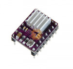
DRV8825 Stepper Motor Driver for CNC 3D Printer (MD0580) Products

| Name | DRV8825 Stepper Motor Driver for CNC 3D Printer |
| Code | MD0580 |
| Price | Rs.400.00 |
| In Stock | Yes |
| Package | MODULE |
Product Details
The DRV8825 is a high-performance carrier board designed to drive bipolar stepper motors. It serves as a drop-in upgrade for the standard A4988 driver module, offering higher voltage capabilities, superior power dissipation, and microstepping resolution down to 1/32-step. It is widely utilized in CNC shields, 3D printer controller boards (such as RAMPS), and custom robotics platforms requiring precise position control.
Specifications
- Motor Supply Voltage: 8.2V to 45V DC
- Logic Supply Voltage: 0V (Features an integrated internal regulator)
- Output Current: Up to 1.5A per coil continuously without a heatsink (Maximum 2.2A with forced air cooling or an attached heatsink)
- Microstep Resolutions: Full-step, half-step, 1/4-step, 1/8-step, 1/16-step, and 1/32-step
- Control Interface: Simple STEP and DIRECTION pins
- Logic Compatibility: Direct interface with both 3.3V and 5V microcontroller systems
- Protection Systems: Over-temperature thermal shutdown, over-current shutdown, under-voltage lockout, short-to-ground, and shorted-load protection
- PCB Architecture: 4-layer, 2 oz copper construction featuring an exposed solderable ground pad underneath the driver IC to maximize heat dissipation
Interface and Pinout Guide
- VMOT: Motor Power Input (8.2V to 45V DC)
- GND (Motor): Power Ground Reference for the motor power supply
- 1A / 1B: Stepper Motor Output Phase 1 / Coil 1
- 2A / 2B: Stepper Motor Output Phase 2 / Coil 2
- VDD: Logic Ground Reference (Tied to the microcontroller ground)
- GND (Logic): Logic Ground Reference
- STEP: Pulse Input for Motor Stepping (Each pulse advances the motor by one microstep)
- DIR: Direction Input (High for Clockwise, Low for Counter-Clockwise)
- ENABLE: Enable Pin (Active Low, turns off motor outputs when pulled High)
- M0 / M1 / M2: Microstep Resolution Selection Pins
- SLEEP: Sleep Mode Input (Active Low, minimizes power consumption when not in use)
- RESET: Reset Input (Active Low, floats or requires pulling High to run)
Key Features
- High-Resolution 1/32 Microstepping: Delivers smoother, quieter, and more precise motor rotation compared to traditional 1/16-step drivers.
- Adjustable Current Limiting: Features an onboard potentiometer to calibrate the maximum current output. This allows the use of voltages higher than the stepper motor's rated voltage to achieve faster step rates without overheating the coils.
- Drop-In Carrier Alignment: Pinout matches the industry-standard A4988 footprint in most aspects, allowing an easy swap on CNC shields and 3D printer motherboards.
- Robust Thermal Management: Built on a heavy-gauge 4-layer copper PCB with an open grounding pad on the underside to pull heat away from the silicon die efficiently.
Common Applications
- 3D Printers: Drives the X, Y, Z axes and extruder stepper motors on boards like RAMPS 1.4 or MKS Gen L.
- CNC Milling Machines: Provides power control for small-scale desktop routers, laser engravers, and automated cutting tools.
- Linear Actuators: Controls automated slider mechanisms, camera dollys, and precise lab positioning stages.
- Automated Pick and Place: Manages small-scale assembly line sorters and component handlers.
Usage Tips
- Current Calibration Step: You must set the current limit using the onboard potentiometer and a multimeter before running the motor. Measure the reference voltage (Vref) between the potentiometer screw and ground, then use the formula: Max Current = Vref multiplied by 2. Overdriving the current will destroy the motor or the driver.
- Power Connection Precaution: Never connect or disconnect a stepper motor while the driver is powered up. Doing so creates high-voltage inductive spikes that can instantly destroy the DRV8825 integrated circuit.
- Heatsink Installation: When operating above 1.5A continuous current, affix a miniature aluminum heatsink to the top of the IC package and position a cooling fan over the board to prevent thermal shutdown.
- Sleep and Reset Bridge: On standard breakout boards, the SLEEP and RESET pins must be connected to each other or pulled High to a 3.3V or 5V logic supply to enable the driver to function.
Sharing is caring, show love and share the product with your friends.
Featured

Other Products
Add to Cart